Sim's Electrical Companion
DC Machines - Motors
Brushed PM DC machines have graphite brushes (1) to provide current to a wound rotor (2) via a split commutator (3). The commutator is split so at each half turn (for each coil) the direction of current is swapped alternate ways to repel against the permanent field magnets - the stator (4). The commutator has a split pair for each set of windings of which there may be numerous or at least two. The illustrations right shows a very simple version of this. Brushed motors are simple to construct, low in cost, easy to control & maintain.
A more recent development is the brushless DC motor. This type have the windings on the stator and the permanent magnets on the rotor. They are more complicated to control and are higher in cost compared with their brushed equivalents. Their advantages compared to brushed motors are higher power for a smaller size, quieter, longer life, less friction heat and higher efficiency.
Motor Winding Arrangements
Motors with windings for both rotor and stator can be assembled in several diifferent arrangements to change the motors characteristics. Factors that can be affected by the design include control, torque, noise, cost, speed, efficiency etc.

Series Wound motors
The stator (field) and rotor (armature) are wired in series and the main characteristic of this motor type is its high starting torque. Both field and rotor have the same current flowing through them as per Kirchhoff's law. This kind of motor can start on load and so is ideal for cordless battery tools like drills, grinders & saws etc. It can be run comfortably at low speeds which allows for fine controlled processes like drilling, turning or tapping threads. Industrial lifting equipment like winches or cranes often employ series wound DC motors. The higher the speed the lower the torque.

Parallel Wound Motors (Shunt)
The field and rotor windings are in parallel so the current is split between the two. Applications include motors that are started off load. For example most bench machinery like lathes, large drill, planers and saws all run up to speed before they are put to work.


Compound Wound Motors
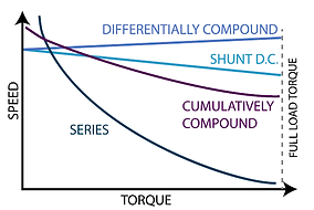
This method employs both series and parallel winding arrangements. Commonly also called shunt motors they are determined to be long or short shunt depending upon the location of the shunt field windings (See diagrams below). Two further categories - cumulatively compound adds to the shunt field. Conversely differentially compound the polarity of the series winding works against the shunt field and an increase in speed is achieved.
DC Machines - DC Generators
DC Generators


The commutator on a DC generator keeps all of the generated emf (Voltage) going in the same direction. At 0° the armature coil is producing little or no potential. At 90° degrees it is at its peak volts emitting and receiving the full push from like poles i.e. N-N S-S. At 180° it is in the opposing position to 0 degrees receiving the lowest amount of force though it may still have inertia. At this point the commutator split switches direction to prevent producing an AC wave form see overleaf. At 270° it is at its second maximum peak which then drops back down to 0 Volts emitting (Ve) at 360° rotation. The commutator is split and then the process goes back to the start.
To lessen the effect of the rise and fall of potential, generators can have many coils on the armature so at any one point at least one coil will be at or near peak. This can all then be filtered to produce a steady DC current as indicated in the illustration with the red line.
To filter the generated signal and produce a perfect ripple free, filtered DC current, some discrete electronics may be used. The simplest method is using a smoothing capacitor. See the section on full wave rectification for more details (Design section).
AC Machines - Motors
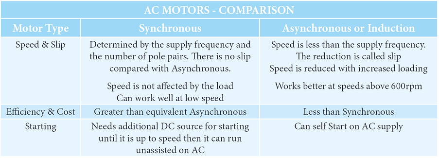
The two types of AC motors are synchronous or asynchronous also known as an induction motor. Synchronous rotor speed is determined by the supply frequency and number of windings. Asynchronous motors run at a speed lower than the supply frequency. The main differences are listed in the table below:

Synchronous Motors
The illustration shows a simple single phase motor. The AC power is transmitted to the coil through brushes and slip rings.
Speed (Ns) is determined by the supply Frequency (f) and number of pole pairs (P).


UK AC is supplied at 50 Hz but I'm sure your aware that not every motor is running at 3000 rpm! This formula demonstrates that motor speed control can be achieved by modifying the supply frequency. This method of speed control is achieved by the use of a Variable Speed Drive (VSD) or Variable Frequency Drive (VFD). This method of control is achieved by converting AC into DC by use of a rectifier. The DC can be easily modulated and then inverted from the DC signal to AC and fed into the motor. There are other methods of speed control discussed in the design section of this book.
One major benefit of a synchronous motor is it will continue to maintain a constant speed irrespective of load. If more load is added it will simply draw more current to maintain the synchronous magnetic fields. This makes it ideal for machines that need to provide a precise consistent rate of movement regardless of their load. Synchronous motors are commonly used in power stations, manufacturing, instrumentation applications, highly accurate mechanical control, production lines, and as a voltage controller.
There are two sub types of Synchronous motors, excited and non exited. Exited require an energised rotor coil to start up and non exited have a magnetised rotor.
The magnetised type are also sub divided into hysteresis, reluctance and permanent magnet types. Hysteresis types are expensive high quality machines with a rotor of a highly coercive hard cobalt steel. Used in robotics, astronautics and servo control.
Coercive have a steel rotor with projecting tooted poles arranged as a squirrel cage rotor which provide additional starting torque.

AC Machines - Generators / Alternators
Alternators are AC Generators. Most commonly known as the means of providing power and charging batteries in military vehicles since World War II. They were introduced into public vehicles in the 1960's. The vehicles electrics are mostly powered by the alternator when the car is running.
The battery is merely a back up and a means of turning over the engine, the alternator does the brunt of the work.
Considering how much they are used over the life of a vehicle, they are very robust and reliable as per a cars starter motors. Both will generally survive the lifetime of a vehicle.

DC AC Generator Comparison
As per DC generators AC Generators come in all shapes and sizes. To save repetition they can also be wired in the same ways as DC types i.e. series, parallel and compound methods. Wound Rotors are connected via slip rings which need less maintenance than a DC commutator as it is a smooth continuous surface. AC generators can have the armature* current on either the rotor or stator whereas DC the armature is rotor generation only. A DC generator has greater loses, maintenance requirements and the output cannot be transformed so easily, however, they are cheaper to construct.
* Armature means conductor of alternating current (even on a DC machine).
As per AC/DC Motors there are two distinct types of AC Generators synchronous and asynchronous (induction) type. Synchronous generators rotate at the induced frequency and asynchronous the current will lag the supplied frequency as will the armature. The lag will affect the power factor and in turn the efficiency. This is why most grid tied generators are synchronous. Though more expensive and difficult to build they more than make up for it for that in efficiency and maintenance factor. Slip rings have longer wear time and do not arc or short like a commutator can once worn.
National Grid and Power Transmission
Most of our grid connected generating stations are synchronous AC generators. This includes Combined Cycle Gas Turbines, Coal fired stations, Biomass generators and hydroelectric schemes & nuclear power. The ease in which voltage can be stepped up and down with very low loses is the major advantage of AC generation. A simple transformer can serve the purpose of stepping up for lower loss, long distance transmission. It can just as easily be stepped down to the variety of supply voltages for end users from heavy industrial at 66kV applications to light domestic at a mere 230V. Note DC transmission can be effective at very high voltages.

AC Machines - Induction Motors - Asynchronous
Asynchronous machines are cheaper to buy and maintain but are little less efficient than synchronous motors. They are however employed for nearly 90% of all motor applications. They are affected by loading and will slow down as the load increases this is a good reason to not overload a lift for example.
Applications for induction motors include lifts, hoists, cranes, pumps, compressors, blowers, travelators, escalators, fans, mills, vacuums and bench machinery like lathes etc.
The diagram below right shows a three phase, 3 pole pair motor. The phase that is closest to peak in the time period attracts the rotor to it. The effect is a rotating magnetic field and can be seen to complete a full rotation once all three phases have completed both positive and negative peaks.
Asynchronous motors can have a wound energised rotor or a ferromagnetic core. In both cases the rotor turns by way of Lenz's law. With a non wound core the field coils magnetic flux cuts across the rotor and induces an emf. This in turn creates a magnetic field that is in opposition to the field that created it! The result is rotation of the rotor due to the repulsing magnetic fields. A wound rotor does the same thing but by way of a field created by the current carrying coils magnetic field working in opposition to the stator windings.
The unwound rotor is arranged like a squirrel cage and is twisted to get the most starting torque possible. Both ends of the cage have conductive shorting rings to increase the current and subsequent magnetic field in the armature. Three phase induction motors create a rotating magnetic field that can self start the rotor. Single phase induction motors need a separate starting mechanism.


Slip
Unlike synchronous motors induction motors are always lagging behind the synchronous speed. This is called slip and is a result of how these motors operate. With this in mind the percentage slip can be considered lag. In fact the current on inductive motors does lag compared with the input voltage this is inductive reactance (XL). To determine the amount of slip as a percentage you can use the following formula:
Slip % = ( (ns - nt)/ ns ) x 100
nt = Rotor speed
ns = Synchronous speed = f/P
f = Frequency in Hertz
P = Pole pairs
Example:
If a motor had 3 pole pairs and had a supply frequency of 60 hertz what would its Synchronous speed be?
ns = Synchronous speed = f/P so 60 / 3 = 20 rps or 20 x 60 = 1200 rpm
If the rotor speed was running at 19 rps then the percentage slip would be:
Slip % = ( (ns - nt) / ns ) x 100 = ( ( 20-19 ) / 20 ) x 100 = 5%