Sim's Electrical Companion
Magnetism & Magnetic Fields
It is virtually impossible to discuss electricity and not involve magnetism the two are so entwined. Any current carrying conductor will create a magnetic field. Conversely any conductor that cuts across a magnetic field will experience an electromotive force. The discovery that magnetism and electricity are two sides of the same coin was by James Clarke Maxwell in the 1890's.
Permanent magnets are always producing a magnetic field. We still don’t really understand what carries the magnetic fields whether there are charge carriers on a sub atomic level or another explanation. Much like gravity it is a fundamental force that we can experience but not fully explain. It is believed that within permanent magnets the electrons are aligned are spinning in the same direction creating a magnetic field.
What we do understand about permanent magnets is that the field produced by a permanent magnet has a few properties that can be defined. In the picture of the bar and horseshoe magnets notice the lines of magnetic flux do not cross.
They are polar and by this we have designated one pole as south and one as north. Much like the earth has an electromagnetic field that is polar. What you might find odd is that the lines of magnetic flux flow from North to south. This essentially means that when a compass is deflected by the Earth's magnetic field it is pointing south. Due to convention in map writing we just paint the other end of the needle red to indicate North!
Like most things in nature opposites attract so when a magnet walks into a bar ... magnet ... North will attract south and south will attract north. If you bring South to South or North to North the lines of flux will compress effectively repelling the opposing magnets.

Permanent magnets are producing magnetic fields because they have been subject to a magnetic field and their magnetic domains have aligned to it. If they were then subject to an opposing magnetic field the process can be reversed. The process of demagnetising becomes easier at higher temperatures as the atoms are more excited.
Iron has a very high permeability and as such is one of the best materials to encourage the growth of a magnetic field. Other elements that make good permanent magnets are, Cobalt, Lodestone and some alloys of rare earth metals including Terbium, Dysprosium & Ferrous Neodymium (a combination of Iron and Neodymium).
Not all ferrous metals are magnetic for example Austenitic stainless steel. Due to the process of creating this stainless steel its micro structure is altered in such a way that it starts out non magnetic. This can be undone by annealing which is a heat treatment process that allows the atoms to relax and become more ductile due to a slow cooling process.
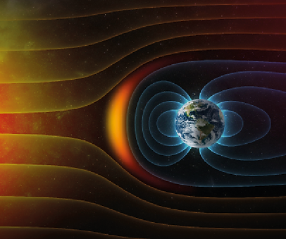
Illustration right to show the Earth's magnetosphere deflecting solar winds which makes life on earth possible.

Maxwell's Screw Rule
When a conductor is carrying current it produces a magnetic field that is proportional to the current it is carrying. This by product can be desirable or not depending upon the circumstances.
James Clerk Maxwell developed a rule that determines the direction of the magnetic field around a current carrying conductor. Aptly named Maxwell's screw rule, he discovered that if a conductor current is travelling away from the observer that the direction of the magnetic field was clockwise and if it was flowing towards the observer it would be anti clockwise.
This is the same as if we were to drive in a standard screw and is a neat method to remember the direction. The illustrations below shows Maxwell’s screw rule for determining the direction of the magnetic field.

As with permanent magnets electromagnets are polar and act in the same way. Like poles repel and opposite poles attract. One big difference is that when the voltage is not applied the magnetic effect of the coil ceases*.
* The ferrous core of the electromagnet may retain a small magnetic effect when the emf is removed.
The strength of an electromagnet is determined by the length of the conductor, its arrangement, properties of the core, temperature and the amount of current being carried by the conductor. See Fleming's left & right hand rules for more detail. To increase magnetic fields we can use a ferrous core and coil the conductor around it to get as much length as is required into a compact form.
The Motor Effect
The motor effect capitalises on the attraction and repulsion of opposing magnets and is used to create a rotating machine. The illustrations below shows how the alignment of magnetic fields can be used for this purpose.
Picture 1 shows how movement can be achieved using repulsion. Picture 2 shows that if the magnetic field is not changed the movement will end at that point. Pictures 3 and 4 show how reversing the magnetic fields at the right time can be used to continue the rotation. This is what a commutator achieves on a DC motor.

The nature of the current applied to the electromagnet is of great importance. DC current will provide a polar magnet that is static. To reverse the polarity of the magnetic field the swap the DC supply conductors.
AC will keep changing polarity at twice the value of the frequency. So for example in the Positive half cycle it may be a N-S magnet but in the Negative half cycle it may be a S-N magnetic field that is produced. This is capitalised upon for frequency based speed control devices and an AC motor's synchronous speed.
Inductance
Self Inductance & Mutual Inductance
Inductance was a term coined by Oliver Heaveside in 1886. Inductance is simply the effect of a current carrying conductor creating a magnetic field. This is also called self inductance. A direct current conductor will have a constant magnetic field that is unchanging. An alternating current carrying conductor will flip N-S S-N at double the sine frequency.
When the magnetic field cuts across a conductor and induces an electro-motive force this is called mutual inductance. The effects of mutual inductance are used in transformers, motors & generators etc.
In distribution of electrical systems this is termed electromagnetic effects. In most cases these are not encouraged as they may cause heating effects which cause power loses and have the potential to damage the system. Heating effects can loosen terminals, melt insulation and in extreme cases destroy the current carrying conductor.
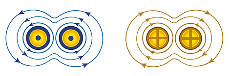
To avoid unwanted magnetic effects in single phase systems we run line & neutral cables together. This keeps the magnetic effects to a minimum and for the most part they cancel each other out see diagram to the right.


If the conductors are carrying current in the same direction and are close enough the magnetic fields will combine and create a larger area of effect. For current carrying conductors this is to be avoided to prevent heating effects as is shown in the diagram to the left.

In three phase systems all the conductors are packaged together in a trefoil formation. The resultant magnetic fields will mostly cancel each other out. This is especially important when the cable is protected by steel wire armour. Steel wire armour is ferrous and as such would act like a core and magnify any magnetic effects.
Cable manufacturers package cables intentionally to minimise magnetic effects. Twin and Earth (PVC/PVC) is arranged purposefully to minimise the magnetic effects as well as placing the uninsulated earth in the centre to increase the chance of carrying a fault current in the case of damage to the cable.
Three core Steel Wire Armour cable (SWA) is arranged in trefoil as are 3 core flexible cables. Cables with 4/5 cores are so arranged that the expected current carrying conductors are as close to each other as possible to cancel out magnetic effects.
Aluminium Wire Armour cables are produced for high current carrying single core conductors. The armour is for mechanical protection and is non magnetic it will not enhance the magnetic field produced by the conductor carrying current.
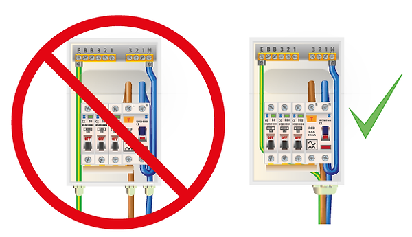
The most common mistake to make concerning magnetic effects is using more than one cable entry for ring final cables or distribution cables entering a ferrous enclosure.
There are a few methods that can be adopted to avoid this. Enlarge the cable entry so all the conductors can enter the enclosure through the same point. Use a plastic plate to replace the metallic entry point or cut between the cable entries in the ferrous material to break the electrical continuity. Note the last method may fail the requirements for IP rating.

Lenz's Law
The Russian physicist Emil Lenz was working on electrodynamics & he formulated Lenz's law in 1834. Lenz's law states that a conductor affected by a magnetic field has an induced electromotive force (emf) which will produce a magnetic field that opposes the magnetic field that created it. A bit of a tongue twister but let me attempt to clarify this using a transformer as an example:
-
Current flowing in the primary coil creates a magnetic field
-
The magnetic field cuts across the conductor of the secondary coil
-
An electromotive force (emf) is induced into the secondary coil
-
The current in the secondary coil also produces a magnetic field
-
The induced secondary magnetic field is in opposition to the magnetic field in the primary coil
As with many of the forces of nature a point of equilibrium is often the natural conclusion in a system. This is also the case with the production of magnetic fields through mutual induction. Energy has been converted but neither created or destroyed within a closed system. This is the principle of conservation of energy, the first law of thermodynamics discovered by Julius Robert von Mayer in 1842.
This is reminiscent of Newtons third law of motion. He stated that an object experiencing a force will repel such force with an equal and opposite amount of energy. Every action has an equal and opposite reaction. In lenz's law. The opposing magnetic field is weaker than the one that propagated it but the remaining energy is the induced emf and heat as well as some far more complex exchanges beyond my knowledge and scope of this site. They do, however, balance the forces of motion, magnetic field and emf that initiated the exchange.
My favoured way of demonstrating Lenz's law is through a set of three very simple experiments that I urge you to try.
1 Send a bar magnet down a tube of PVC. As an insulator a current cannot be induced into the tube so no electromagnetic force is experienced. The magnet falls through the tube at the expected rate close to the acceleration due to gravity excluding any opposing forces like friction and air resistance.
2 Send the same magnet down a steel tube of the same length, diameter and thickness. In this case the permanent magnetic field is far stronger than he weak force of gravity and the magnet just attaches to the top of the tube because it is a ferrous metal.
3 Lastly send the same magnet down a copper tube of equal proportions. This is where lenz's law becomes apparent. The magnet induces an emf in the copper which produces a magnetic field that is in opposition to the permanent magnet. The opposing magnetic field is not sufficient to stop and hold the magnet so it falls but at a greatly reduced speed.
You could apply this principle to confuse Bat the Rat players!

Lenz's law has the effect of reducing the efficiency in electrical components that make practical use of mutual induction. Motors, generators and transformers in distribution system are especially effected and are so designed to minimise the negative effects of lenz's law.
One example of how this is achieved is by laminating iron cores to reduce eddy currents in the iron core and therefore reducing back emf produced by unwanted magnetic fields. This in turn reduces the heat produced by the core which in turn reduces the resistance due to temperature in the windings. Other methods include the physical design, the use of non conductive materials or incorporating shielding to reduce unwanted magnetic effects.
