Sim's Electrical Companion
Resistors in Series & Kirchhoff's law
When adding resistors together in series the method is to simply add their values together. This applies to AC or DC circuits. As mentioned earlier be careful to take into account metric prefixes.

Application of Ohm's Law - Resistors in Series
Using the three examples above with voltage applied we can determine the total current flowing through the circuit. The supply voltage has been set at 165 Volts to calculate the total current (It) divide the supply voltage (Vt) by the total resistance (Rt) of the circuit,
The Equation is It = Vt / Rt:
The current in the first circuit would be: 165V / 55Ω = 3A
Kirchhoff's Law - Series Circuits
Next we can apply Kirchhoff's law for series circuits. Kirchhoff determined that the total current in a series circuit is experienced by every component in the circuit. He also determined that every component in the circuit had a volt drop across the components that added up to the total voltage applied to the circuit.
Using the examples from above we can now determine the values of the volt drops across each component. The equation uses Ohm's law and requires us to know the total voltage and current in the complete circuit and the value of each resistive load.
So in the example illustrated below we have three resistors with values of 10Ω, 15Ω & 30Ω. To ascertain the volt drop across each resistive component multiply the value of the resistor by the total current in the circuit:
The first resistor has a volt drop of: V1 = R1 x It = 10Ω x 3A = 30V
The second resistor has a volt drop of: V2 = R2 x It = 15Ω x 3A = 45V
The third resistor has a volt drop of: V3 = R3 x It = 30Ω x 3A = 90V
If you add the three values together they should all sum up to the total voltage (Vt).

Parallel Resistance & Kirchhoff's Law
With parallel circuits the calculation of total resistance requires the use of reciprocal values. This simply means each resistor is divided by 1. Most importantly the resulting sum is also a reciprocal.
To describe this in a formula, the total resistance of three parallel loads can be determined by:
1/Rt = 1/R1 + 1/R2 + 1/R3 ..... or 1 / (1/R1 + 1/R2 + 1/R3 .....)
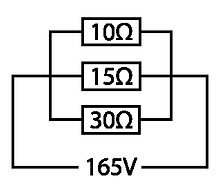
The example to the left has three resistors 10Ω 15Ω & 30Ω. They are connected in parallel and the total resistance is vastly different compared to series connection.
1 / ( 1/10 + 1/15 + 1/30 ) = 5 Ω
A shorter way of calculating the total resistance is to use the reciprocal key of a scientific calculator X-1

Application of Ohm's Law - Resistors in Parallel
Using this example with a supply voltage applied we can determine the total current flowing through the circuit. I have set the supply voltage at 165V to show the difference in the arrangement of parallel and series circuits on these two pages. As with a series circuit calculating the total current (It) is the same process.
Divide the supply voltage (Vt) by the total resistance (Rt) of the circuit:

It = Vt / Rt = 165V / 5Ω = 33A
Kirchhoff's Law - Parallel Circuits
We can apply Kirchhoff's laws for parallel circuits. Kirchhoff determined that the total current in a parallel circuit is split between the number of legs in the circuit and is proportional to the resistance of each leg. The total current (It) equals the currents drawn through each leg. Using the example from above we can now determine the current flowing through each of the resistors. Once again we refer to Ohm's law, this time we need to know the value of each resistive load and the total voltage (Vt).
We have three resistors with values of 10Ω, 15Ω & 30Ω. To ascertain the current drawn by each resistive component divide the value of the resistor by the total voltage in the circuit:
The first resistor draws a current of: It = Vt / R1 = 165V / 10Ω = 16.5A
The second resistor draws a current of: It = Vt / R2 = 165V / 15Ω = 11A
The third resistor draws a current of: It = Vt / R3 = 165V / 30Ω = 5.5A
The total circuit current (It) is the sum of the three values:
So: 16.5A + 11A + 5.5A = 33A = It
Kirchhoff's law for parallel connected loads is that each of the legs of the circuit are subject to the same electromotive force (Voltage). So expressed as a formula: Vt = V1 = V2 = V3 .... etc.

Compound Resistance
Calculations Involving a Combination of Parallel & Series Resistors
Most circuits have a combination of series and parallel loads. To calculate current, voltage and resistances of sections of compound circuits Ohm's law and Kirchhoff's laws still apply as described in the previous two pages. The process requires the designer to designate what parts need to be calculated as separate entities before applying final calculations to the entire circuit.
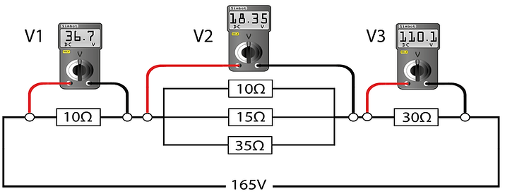
In the example below we have five resistors with a combination of series and parallel connections:

It is easier to calculate how current, resistance and voltage is divided among the five resistors if it is considered as three entities before adding them all together. The parallel section has three resistors:
1 / ( 1/10 + 1/15 + 1/30 ) = 5 Ω
Now we have the total resistance of the parallel section we can treat it like a single resistor and add it to the other two series connected resistors. Alternatively you can add them all in one. Three methods are shown below:

Next the total current (It) can be calculated using Ohm's law:
It = Vt / Rt = 165V / 45Ω ≈ 3.67 A
This can now be applied to the three sections of the circuit to determine the volt drop across each section:
The first resistor has a volt drop of: V1 = R1 x It = 10 Ω x 3.67A ≈ 36.7 V
The second resistor has a volt drop of: V2 = R2 x It = 5 Ω x 3.67A ≈ 18.35V
The third resistor has a volt drop of: V3 = R3 x It = 30 Ω x 3.67A ≈ 110.1V
Total Voltage is the sum of the volt drops: V1 + V1 +V1 = 36.7V + 18.35 + 110.1 ≈ Vt ≈ 165V
The application of this is essential to circuit design. It is covered further in the design section, common circuits.

Complex Compound Resistance - The Resistor Cube Problem
The resistor cube is a physics problem that has been in play for some time but I must attribute my first meeting with this problem as it was posed in the book Professor Povey's perplexing problems. I highly recommend it for those of you who like a metal challenge in maths and physics. It has a variety of challenges some of which I admit are beyond my level of understanding.
This problem is simple to solve when you know how but I like the way it makes you think of the problem in a novel way. The cube is made up of 6 Ω resistors on each and every leg. To determine the total value of resistance from point A to point B may at first seem a little daunting. You need to convert the 3d shape into a 2 dimensional problem.

The first intersection from point A links to three 6 Ohm resistors.
Using the rules for parallel resistance we know that as they are the same value we can divide 6 Ohms by three.
So the first leg is: 6 / 3 = 2 Ω
The second part of the puzzle we can see that each of the three legs connect to pairs of resistors. In the central section there are six 6Ω resistors in parallel.
So in the central section we have:
6 / 6 = 1Ω
The final section connecting to point B is once again 3 resistors in parallel so we have the final piece of the puzzle. They can now be added together as if they were three resistors in series.
2Ω + 1Ω + 2Ω = 5Ω

In virtually all circuits there are problems such as this. The point that needs to be made is if you break it down into manageable chunks, you can strip away some of the complexities, much like life!
Resistor Pyramid Algebraic Challenge
Considering the method of finding the total resistance of the resistor cube. Let me pose a new problem:
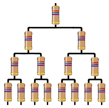
A pyramid starts at the first level with a set value resistor. The next level adds two more of the same value resistors per node as shown. Consider every level increases by an extra two resistors per node.
Challenge:
Come up with an algebraic method of determining the total resistance (rt). This is based on 'n' where n is the number of levels in the pyramid and r being the set value of the individual resistors.

