Sim's Electrical Companion
Transformer Construction, Types & Calculations
Single Phase Transformers
A transformer is a simple device that changes a primary voltage / current into a secondary voltage / current. The method of achieving this is so simple, a primary source conductor current produces a magnetic fields and is wound around an iron core to increase its subsequent magnetic field. The lines of flux cut across a secondary winding which induces an emf in the secondary circuit. The secondary voltage will be dependant upon the ratio of windings primary and secondary. If there are an equal amount of windings on both sides the transformers output and input will be the same (excluding loses). If the secondary windings are lower the transformer is considered to be a step down transformer. If the secondary windings are greater than the primary windings it is a step up transformer.


Transformers have a ferrous core which increases the magnetic field produced by the primary coil. There are three common types of core construction Shell, Core and Toroid (pictured right). The toroid has the secondary windings wound over/under the primary windings. Shell and core types the windings are clearly separated.


Basic Mechanics - Force & Energy
Isaac Newton laid down the fundamental laws governing basic mechanics regarding the macroscopic universe. His three fundamental laws of motion are:
1. An object remains at rest or moves at a constant velocity unless acted upon by a force.
2. An objects force is the product of its mass x acceleration.
3. Action / reaction, an object that experiences a force exerts an equal and opposite force.
In these simple sounding terms we can predict the behaviour of planets, universes or snooker balls. Even though Einstein's theory of general relativity finesses Newtonian physics, Newton's theories are still the basis for which most space exploration and expedition is based upon.
The second law states that:
Force = mass x acceleration
F = ma
Force = Newtons (N)
Mass = Kg
Acceleration = metres / second squared
1 Newton = Force required to move a mass of one kilo, one metre in one second².

On Earth all masses are subject to the Earth’s gravity. At sea level this acceleration is approximately 9.80665 m /s². This is often rounded to 9.81 m/s² which is accurate enough for most purposes. The further away you are from the centre of the earth the lower the gravity.
Potential Energy (PE)
Potential energy is the amount of stored energy a mass has when it is suspended and subject to a force of gravity. The amount of potential energy is calculated using the following formula:
PE = m x g x h
PE = Potential Energy in Joules (J)
m = mass in Kg
g = gravity (m/s2)
h = height in metres (m)
Some time ago ago I did a sky dive and my weight was about 68kg. Given the height of 13,000 feet (3962.4m) and gravity taken as 9.81m/s² the potential energy I had was:
PE = 68 x 3962.4 ≈ 269,443 Joules
Given that 1 Joule = 1 Watt / second it is a staggering amount of energy - I would highly recommend it!

Falling Objects
In legend Galileo is said to have dropped two dissimilar cannonballs from the top of the Leaning Tower of Pisa. They both landed at the same time proving that mass had no effect on their velocity. He did dispel Aristotle’s theory that an objects mass plays a part.
In the case of falling in an atmosphere the velocity m/s will increase exponentially up to the point of terminal velocity. This is where the forces acting against gravity reach an equilibrium so the graph would level out. Examples include air resistance, atmospheric disturbances, thermals, air density and the shape & consistency of the falling body.
The graph shows the velocity and distance travelled by a mass subject to earths gravity that is in a vacuum and has no other forces acting against it.
Velocity = Acceleration x Time
Distance = ( Acceleration x Time² ) / 2
Basic Mechanics - Work done
It is essential for designers of mechanical or electrical systems to determine how much effort is required to achieve the desired effect. For example it would be madness to expect a toothbrush motor to run a crane and vice versa.
The starting point of determining the required amount of power is Work Done.
Force = mass x acceleration
F = m x a
Work done = force x distance
Wd = f x d
Force = Newtons (N)
Mass = Kg
Acceleration = m/s squared
Work done = Newton Metres (Nm) or Joules (J)
Distance = metres
Example:
To Lift a drum of cable that has a mass of 250kg, 3m at sea level. We can establish the amount of energy required to achieve the lift:
F = m x a = 250 x 9.81 = 2452.5 N
Wd = 2452.5 x 3 = 7357 Joules
This is equal to the amount of PE potential energy the drum would then have!
A motor or hoist would need to be able to withstand not only the force of 2452.5 Newtons it would also need to generate 7357 Joules or more to achieve the lift undamaged. This kind of information is essential for designers and engineers to adequately design lifting systems.

Efficiency
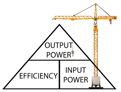
In an ideal world the above example needs 7357 Joules to achieve the lift. Sadly inefficiencies affect all systems this needs to be taken into account. Friction, heat, air resistance, electrical resistance, poor design and transfer losses are all examples of where these inefficiencies creep in. To work out the efficiency of a system simply divide the output power by the input power and multiply by 100 to give a percentile figure.

Example 1: A 5kW motor draws 25A on a 230V supply
Using power law we can establish:
P = I x V therefore P / V = I 5000/230 = 21.74A
Output power / input power = 21.74 / 25 = 0.8696 x 100 = 86.96 % efficient
The cable lift above needed 7357 Joules therefore if the machine was 86.96 % efficient you need to rearrange the equation for input power:
(Output power / Efficiency) x 100 = Input power = (7357 / 86.96) x 100 ≈ 8460 Joules
Example 2: A cargo lift motor needs to lift a 500kg car and has a capacity for lifting 2000kg. The motor has a power factor or cos φ of 0.81 another way of saying 81% efficient. If the lift shaft is 25m the work done to achieve a full load lift from the bottom to the top would be:
Work Done = Force x Distance = 2500kg x 25m = 62500 Joules
Taking into account the efficiency rating of the motor: 62500 J / 0.81 ≈ 77160 Joules
Another consideration that engineers will allow for is other factors that will increase the input requirements further like air resistance, frictional forces and maintenance factor in many cases this is stated at 80% of peak. If the additional factor was 80%
the input power would be 77160 / 0.8 = 96450 Joules to provide an output of 62500 Joules.
Mechanical Advantage - Levers
A lever offers the mechanical advantage of either increased movement or greater applied force. This is called a mechanical advantage. As you don't get something for nothing the advantage is gained by the length of lever and how it is positioned. There are three classes of lever that offer different advantages but they all have a point where load is applied a fulcrum and a point where effort is applied to manipulate the load. The three types are classed by the arrangement of these three things.
Class 1 lever
This is probably the most commonly used lever. Examples are scissors, see saw, beam scales, wire cutters, crowbar, bot oars and hammer claws etc. The lever has the load on one end the fulcrum in the middle and the effort on the other end. The further the effort is from the fulcrum compared to the load to fulcrum the easier it will be to lift the load. In the case of beam scales or a see saw you may have noticed if the mass is the same on both sides both sides will level out. The ancient Egyptians used this knowledge in building their massive structures.
Class 2 lever
The most common class 2 lever is the wheel barrow other examples include nail clippers, foot pumps and bottle openers. In all these examples the effort is at the opposite end to the fulcrum with the load in the middle. This type of lever increases the effort force.
Class 3 Lever
This lever reduces the effort applied to the load but increases the distance moved. Examples include fishing rods tweezers, human arms & legs, Garden fork / spades and a broom. The effort is between the fulcrum and load. The illustration shows tweezers are in fact two class 3 levers.
Examples of Mechanical Advantage
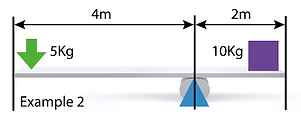
In the first example illustration you can see a balanced system. The load and effort are the same because the distance from the fulcrum of the load and effort are the same. The ratio of this example is 1:1. To get a mechanical advantage the load to fulcrum distance must be smaller than the effort to fulcrum distance.
Second Example
In this second example we can see the benefit of adding distance to the effort side. The ratio reduces the amount of effort required to affect the load.
In this case doubling the distance on the effort side halves the effort required to move the load. If it were three times longer the effort could be one third the effort of the load.
The ratio of this lever is 2:1 (4 / 2 = 2). You can check it is correct by multiplying distance and load on both sides.
They should balance 4x5 = 20 : 2x10 = 20.
Archimedes supposedly said:
"Give me a lever long enough and a fulcrum on which to place it and I shall move the world."
The world has an approximate mass of 5.9 x 10^24 kg so the mechanical advantage required is quite significant! In essence the sentiment is true if a material could be rigid over that distance.


Mechanical Advantage - Pulleys
Single Pulley System
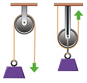
Like levers pulley are used to create a mechanical advantage or to simplify a process. When only one pulley is employed it may seem easier to lift but in fact there is no mechanical advantage. When using a single pulley the same amount of force is required to hold the load and more force is required to move the load. As far as the distance the load and effort travel they would be the same for both the illustrated examples of a single pulley system. As well as mechanical advantage pulleys can also be used to change the direction of travel.

Two Pulley System
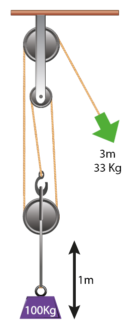
Where two pulleys are employed the mechanical advantage is 2:1. This equates to the effort required to lift the load will be divided by two so in the example the 100 Kg load would need an effort of 50 Kg to lift it. In physics you never get something for nothing. In the case of the mechanical advantage the distance travelled by the effort would be twice that of the distance travelled by the load. So in the example to move the load 1m the effort must move 2m.
The same as the lever system the product of load x distance and effort x distance should be the same:
In the example the 100 Kg load moves 1m so: 1 x 100 = 100
The effort applies a force of 50 Kg over 2m so: 2 x 50 = 100
Three or More Pulley Systems
I think you may have guessed now that the mechanical advantage is the amount of ropes or pulley other than the effort rope. So three pulley will have three load bearing ropes and one effort rope. The ratio is three to one 3:1 so the load can be lifted with one third of the effort but the effort rope must travel three times the distance that the load travels.
An average saloon car weighs 1500 Kg
The average 5' 10" man is about 75kg
1500 / 75 = 20 Pulleys
With a 20 pulley system a man weight could lift a saloon car with his weight. He will have to move 20 times further than the car. A compact way of having multiple pulleys is to combine them in a block and tackle pictured below.

Three Main Types of Pulley
A fixed pulley is secured to the fabric of a boat or building or crane for example.
A moveable pulley is one that also travels as well as the load when in use.
A compound pulley is a combination of both fixed and moveable pulleys as used in a block and tackle.
Mechanical Advantage - Cogs & Chains
Much like pulleys cogs can be used to change direction or type of motion and to gain a mechanical advantage. As per pulleys mechanical advantage is gained at the cost of distance moved. To convert rotary motion to linear motion a rack and pinion can be employed see illustration. In reverse the rack and pinion would change linear in to rotary motion.
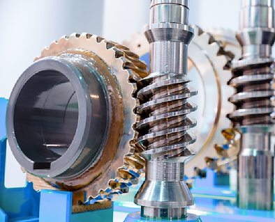
To change the angle of rotary motion by 90 degrees a worm gear can be used. To get angles less than 90 degrees gears can be used where both gears have half of the angle that is required. If 45° degrees was required both helical gears would be 22.5°.

Mechanical Advantage
In a two cog system, like on a bicycle, the gears may be meshing together or connected by a chain. If they have the same diameter and amount of teeth both gears will travel the same distance at a synchronous speed. To the right this simple system of two gears provides a mechanical advantage of 2.75:1. This is determined by dividing the driving gears teeth by the driven gears teeth. What this means is the rear sprocket is doing 2.75 revolutions for every single revolution of the drive gear.
To achieve this the drive gear cog has to travel 2.75 times more distance than the driven gear. This ratio is equivalent to the outer circumference of each gear so it also applies to pulleys connected by belts. The ratio could be determined by either the two circumferences or radii.
On a bicycle it is common to have the large gears at the front and the rear gears driving the rear wheel. Anyone who has used a bicycle with gears will know how much of a difference they make to tackling big hills. High gear is where the largest front chain ring is in use along with the smallest rear sprocket. On my own bike this ratio is 50/11 ≈ 4.54 so the rear wheel travels 4.54 times for every full pedal stroke perfect for high speed and downhill riding. The lowest gear on my bike is 34/32 = 1.06 which is very close to synchronous speed and distance. This is more suitable for going uphill or riding on slow difficult terrain.

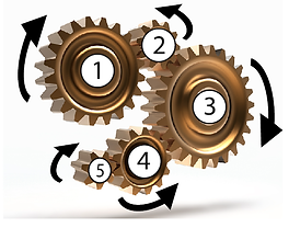
Cogs in Motion
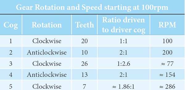
Where cogs are in direct contact they will rotate in the reverse to the adjacent cog. The illustration is a simple linear arrangement of five gears. From the example right we can draw quite a few conclusions given a little bit of information. The table is based on starting clockwise at 100 rpm. After 4 transitions the end result is a clockwise rotation of 286 revolutions per minute.
