Sim's Electrical Companion
AC Power - True, Apparent & Reactive Power
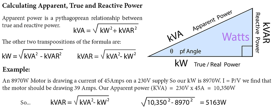
Reactive elements increase the resistance in an electrical system and as a result they increase the amount of power required to run the machine/system. These reactive loses are due to capacitive or inductive loads and cause more power to be drawn and used than is truly required to run the machine.
A common analogy for this lost power is the humble pint. The bit you want is the beer we will call this True Power (kW). The froth is the waste and we will call this Reactive Power (kVAR). Finally you have to buy the whole package this is Apparent Power (kVA).
If you were served a pint and half of it was froth I'm sure you would not be best pleased to pay for it. The same applies to electrical systems you have to pay for the reactive even though it is not doing any useful work.

It is not entirely true that there is no use for reactive power, it is essential for the operation of transmission and distribution systems and in regulating a supply. For the purpose of this volume I am going to overlook that and just deal with unwanted reactive power in final circuits.
Lets focus on reactive elements that we do not want. In any electrical system that has capacitive or inductive loads there will be power losses due to the inductive or capacitive reactance. If the loss is inductive current will lag voltage and if it is capacitive the current will lead the voltage, both create a loss in useable power.
Power being the product of voltage and current it is easily described by the three graphs below. It is It is clear that only the pure resistive circuit gives coherent power in phase with the current and voltage.


Power Factor p.f.
Efficiency in electrical systems is always a hot topic in electrical engineering. Most of our systems are inherently wasteful so the more we can do to improve efficiency the better use will be made of the energy we have at our disposal. Including lowering the overall carbon foot print.
Efficiency in electrical machines is quoted as a decimal called power factor (pf) or percentile figure for efficiency. It is a ratio of what energy you get out compared to the energy you put in. For example if a machine was 80% efficient its power factor would be 0.8 & if the machine were 100% efficient it would have a pf of 1 also called parity.
Power factor can be lagging or leading depending upon the nature of the loading be it more capacitive or inductive. The current in an inductive load will lag Voltage by up to 90 degrees. Conversely the current in a capacitive load will lead the voltage by up to 90 degrees. There will always be some resistance so 90 degree lead or lag is not possible. Power factor can be determined in a couple of ways:
1 - Measure current being drawn by the machine and compare with its rating in Watts.
2 - or Divide KW by KVA to determine the ratio. This can be multiplied by 100 to give a percentile figure.


Example 1
A 7.5 kW motor draws a current of 40 Amps. Using Power law: P = I x V
We can determine 7500W / 230V should be drawing a current of 32.6 Amps.
So the motors power factor = pf = 32.6A / 40 = 0.815 or cos φ 0.81
or (pf x 100) = 81.5 % efficient.
Example 2:
A 12 kW three phase motor has a stated power factor of 0.86 calculate the most appropriate protective device for the device allowing for high starting current, voltage and its power factor.
Three phase power can be calculated using the formula: P = √3 pf I V

The machine needs a C type breaker to allow for inrush currents on start up. 12,000 Watts on a three phase supply could be protected by a C32 circuit breaker if it was 100% efficient. However the 0.86 power factor brings the current drawn up to 35A so select the next common rating up, likely be a B40 circuit breaker or a 40 Amp HBC Fuse. Motor manufacturers are required to give details about the motor on an information example illustrated below.
Note it states the expected voltage, current draw and power rating. Additionally it may either state its expected efficiency under full load as a percentile figure or it will be stated as the cos angle which often indicated by the symbol phi φ in this example 0.86-0.89.
Some motors will have information for more than one frequency as this will affect their p.f. & current draw.

Power Factor Correction
Power factor correction relies on inductance and capacitance being opposite types of reactance. If a circuit is has too much inductive reactance it can be brought closer to parity (100%) by use of a capacitor or vice versa as shown in the diagram below if the balance is calculated well the circuit will behave more like a resistive load.

As it is a reactive element that fluctuates it is difficult to achieve perfect power factor in a passive system. It may get very close to parity (100% efficient) if the correction is monitored and automatically controlled.
Calculating Power Factor Correction Capacitors
Once you have either measured or calculated kVAR you can then determine what size capacitor would be required to correct or at least improve the power factor and bring it closer to parity.
To calculate the capacitor size we need the supply voltage (V), reactive power (kVAR) & supply frequency (f). And the equations for power and capacitive reactance.
In the example on the previous page we had a motor with a power factor (pf) of 0.86 and a true power (kW) of 12kW which gives an apparent power (KVA) of 12000/0.86 = 13953W and a kVAR of:

The voltage is √3 x 230 = 398V three phase now we can work out the capacitive reactance (Xc) in Ohms:


Now for the final calculation - What value capacitor is required in Farads:

Power Factor Correction - Equipment
Pictured is an example of power factor correction equipment. The top shows the capacitors (silver cans) and the control relays. The bottom shows an automated digital control system which can be manually overridden. It has warning lamps for low power, high power, low current, high current, low voltage, high voltage, overload, high temperature & voltage present.
Currently it is showing 87% efficiency with high power consumption and low current. A system like this can work with a building management system and keep records of the building services use, efficiency and provide remote access to the controls.
