Sim's Electrical Companion
Inductive Reactance XL
An inductor is a coil of conductor that is so arranged to purposefully create a magnetic field. Inductors include chokes, ballasts, motor windings, transformer windings & solenoids etc. Inductors react to the rate of change in current so they are only affected by AC current and as such are sometimes referred to as an AC resistor.
(* 90⁰ is a theoretical scenario. It is not possible for there to be no pure resistance in a circuit however it may be very low.)
Lenz’s law states there is some back emf (electro-motive force) produced by the intended magnetic field which opposes current flow. This reactive element is called inductive reactance and it causes a phase shift where current lags voltage by up to 90 degrees*. The Sine and phasor diagrams below show the effect of inductive lag. The lag of current compared with voltage is called a phase shift.

In some cases we need to manufacture a phase shift for example in the working principles of motors. In most cases the phase shift increases overall resistance, power drawn & reduces the efficiency of the electrical system. This can be countered by the addition of a power factor correction capacitor.
The SI unit for inductance is Henry, unit symbol (H), Named after Joseph Henry who did extensive work on inductors, electromagnets and motors in the 19th century. When an alternating current of a constant frequency of 1 ampere per second a 1 Henry inductor will have a volt drop across it of 1 Volt.
To determine the equivalent resistance (Ω) caused by the inductive reactance. The following formulas is used which takes into account frequency, rotation and the value of the inductor:

Adding Inductors Connected in Series and in Parallel
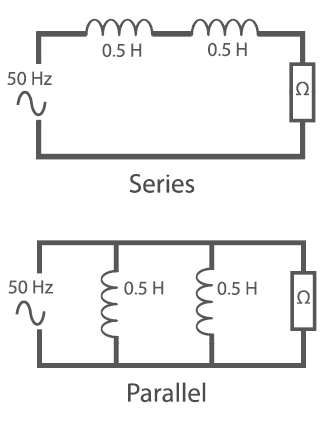
Inductors are added together in series or parallel in the same manner as resistors. In series they are simply added together and in parallel the reciprocals are added.
In series the total inductance
= 0.5 + 0.5 = 1H
XL = 2π f l = 2π x 50 x 1 ≈ 314 Ω
In parallel the total inductance = 0.25H
Total resistance =
XL = 2π f l = 2π x 50 x 0.25 ≈ 78.5 Ω

Capacitors & Capacitive Reactance Xc
Capacitors are another type of component that have a reactive element that affects resistance this is called capacitive reactance (Symbol Xc). A simple capacitor is constructed from two conductive plates with a dielectric insulator between them. The dielectric does not conduct across itself when an electromotive force is applied it polarises and stores charge (similar to rubbing a balloon on a jumper).
When the current that was applied is removed the charge is then released from the capacitor back into the circuit until the capacitor is back in a state of equilibrium or rest. So a capacitor can be thought of as a kind of as a charging and discharging battery. The Diagrams below show a simple capacitive circuit, the effect on the sine and its phasor diagram. The phasor is leading by up to 90 degrees. 90 degrees is not feasible unless the pure resistance can be removed entirely. (A subject being researched in the process of superconductivity)

The effect a capacitor has on the load sine is shown in the two diagrams (Right). To make the example easier to read both sides of the sine are shown on the positive half cycle*. (* See Full wave rectification in the Design section to see how this is achieved with the use of diodes).

On the left is the supplied sine wave and on the right is the effect of the charging and discharging of the capacitor on the sine. It can be seen from this how capacitors can be used for voltage regulation which is discussed in the design section.
The symbol for capacitive reactance is XC and is measured in Ohm's. To determine the amount of reactive resistance the capacitive circuit generates the following formula is required:
Xc = Capacitive reactance = Ω
2π = Rotating change in current
f = Frequency = Hertz = Hz
c = Capacitance = Farads = F
Example:
A 22 micro farad (µF) capacitor is connected to a 50 Hertz supply. Calculate the capacitive reactance in Ohms:
Xc = 1/ (2π f c) = 1 / (2π x 50 x 22x10-6) ≈ 144.68 Ω
Adding Capacitors Connected in Series and in Parallel
As per resistors a great many values can be achieved using standard value capacitors in a combination of parallel, series or compound connections.

Unlike resistors and inductors capacitors are added together in value when they are connected in parallel. Conversely when connected in series the reciprocal of the sum of reciprocal values is the total value.
Example:
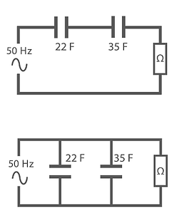
Two Capacitors with values of 22 F and 350 F are connected in series and parallel calculate the total capacitance for each arrangement:
Series = 1 / (( 1/22 F) + (1/35 F)) = 13.5 F
Parallel = 22 F + 35 F = 57 F
Z: Impedance - Ω
Over the previous two pages we have looked at how to calculate the amount of reactance in capacitive and inductive circuits. The total resistance in a reactive circuit is called Impedance (Z) measure in ohm's. This takes into account pure resistance, capacitive reactance and inductive reactance. The relationship is Pythagorean and the equation is:

Interestingly it makes no difference if XL and Xc are swapped around - It will give the same answer! The transpositions of the formula are as follows:

As can be seen if there is either no capacitance or inductance then that may be omitted.
Example 1:
Adding Inductive Reactance and Pure Resistance
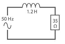
In this circuit we have a 35Ω resistor with a 1.2 Henry Inductor. To calculate the Total impedance we must first calculate the Inductive reactance (XL).
Inductive Reactance XL = 2π f l So: XL = 2π x 50 x 1.2 ≈ 377 Ω

Example 2:
Adding Capacitive Reactance and Pure Resistance
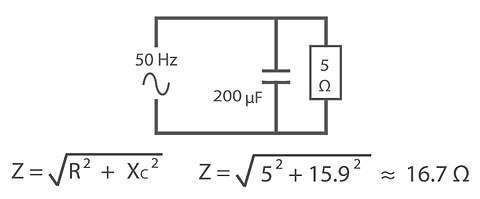
In this circuit we have a 5 Ohm resistor with a 200 micro Farad capacitor. To calculate the Total impedance we must first calculate the capacitive reactance (Xc).
Capacitive Reactance Xc = 1 / (2π f c)
So: Xc = 1 / ( 2π x 50 x 200x10-6) ≈ 15.9 Ω
